Executing an Instruction Step-
The following diagram is a simplified version of the processor. It contains only
those components and data paths necessary for a register-
Note that these is no data memory. That is required only for load and store operations.
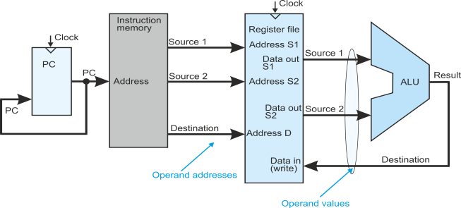
In this figure data flows from left-
The data flow is:
- Program counter to instruction memory (look up the next operation)
- Instruction memory to register file (look up the operands, the data, required by the current instruction)
- Register file to ALU (perform the required operation on the two operands)
- ALU to register file (store the result from the ALU back in the register file).
Note how the register file does a double duty. First look up the operands and then store the result.
To see the sequence of operations and timing, click the blue link.